File:Dipole antenna standing waves animation 1-10fps.gif
From Vigyanwiki
Dipole antenna standing waves animation 1-10fps.gif
Dipole_antenna_standing_waves_animation_1-10fps.gif (682 × 311 pixels, file size: 170 KB, MIME type: image/gif, looped, 20 frames, 2.0 s)
This file is from Wikimedia Commons and may be used by other projects. The description on its file description page there is shown below.
Summary
| DescriptionDipole antenna standing waves animation 1-10fps.gif |
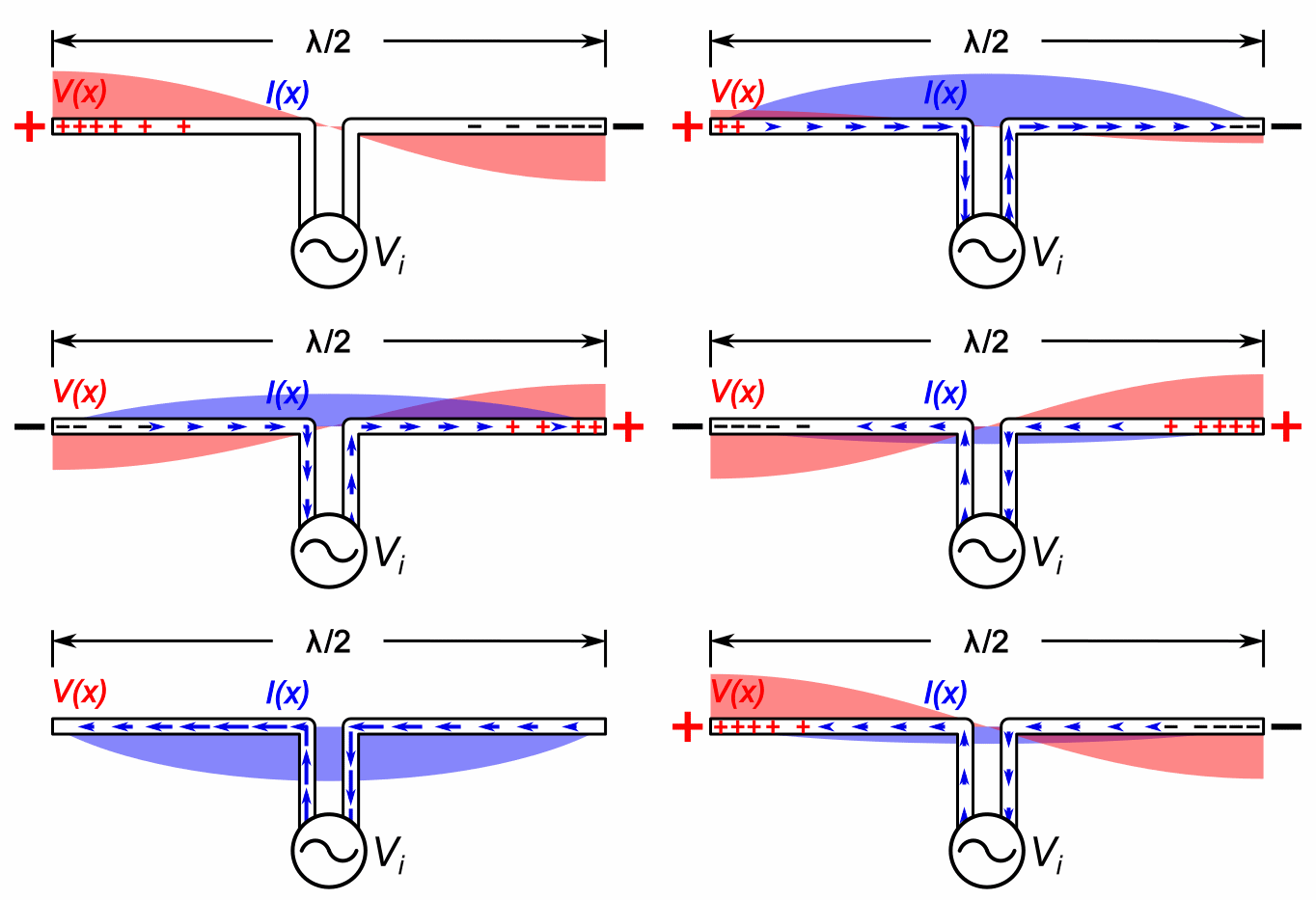
English: Animation showing standing waves on a half-wave dipole antenna driven by a sinusoidal voltage VO from a radio transmitter at its resonant frequency. The oscillating voltage pushes the electrons back and forth along the two metal rods that make up the antenna, creating oscillating currents (blue arrows) in the antenna, charging its ends alternately positive (+) and negative (-). Since at this frequency the antenna is a half wavelength (λ/2) long, a sinusoidal wave of voltage or current takes exactly one cycle to make the round trip from one end of the antenna to the other and back, so the reflected waves reinforce each other. The antenna acts like an electronic resonater. Waves of current and voltage reflecting back and forth between the ends of the rods interfere to form standing waves. The standing waves are shown graphically by bars of color (red for voltage V(x) and blue for current I(x)) whose width at each point is proportional to the amplitude of the wave at that point. There are voltage antinodes (maxima) and current nodes (zero points) at each end, where positive (+) and negative (−) charges accumulate alternately each half cycle, while there is a voltage node and current antinode at the drive point in the center. The large oscillating voltages and currents on the antenna at resonance causes it to radiate maximum radio wave power. The zero voltage reference for the voltage waves, as is customary in these graphs, is halfway between the voltage on the two transmission line conductors. The blue arrows show the direction of conventional current, flow of positive charge; the direction of flow of the electrons in the antenna is opposite to the arrows. The oscillations are shown slowed down enormously; the current in actual radio antennas oscillates back and forth between ten thousand and one billion cycles per second. |
| Date | |
| Source | Own work |
| Author | Chetvorno |

|
This circuit image could be re-created using vector graphics as an SVG file. This has several advantages; see Commons:Media for cleanup for more information. If an SVG form of this image is available, please upload it and afterwards replace this template with
{{vector version available|new image name}}.
It is recommended to name the SVG file "Dipole antenna standing waves animation 1-10fps.svg" - then the template Vector version available (or Vva) does not need the new image name parameter. |
Licensing
I, the copyright holder of this work, hereby publish it under the following licence:
| This file is made available under the Creative Commons CC0 1.0 Universal Public Domain Dedication. | |
| The person who associated a work with this deed has dedicated the work to the public domain by waiving all of their rights to the work worldwide under copyright law, including all related and neighbouring rights, to the extent allowed by law. You can copy, modify, distribute and perform the work, even for commercial purposes, all without asking permission.
http://creativecommons.org/publicdomain/zero/1.0/deed.enCC0Creative Commons Zero, Public Domain Dedicationfalsefalse |
Captions
Add a one-line explanation of what this file represents
Animation of standing waves on a dipole antenna
Items portrayed in this file
depicts
6 June 2015
File history
Click on a date/time to view the file as it appeared at that time.
| Date/Time | Thumbnail | Dimensions | User | Comment | |
|---|---|---|---|---|---|
| current | 10:30, 9 July 2020 |  | 682 × 311 (170 KB) | wikimediacommons>Chetvorno | Improved current arrows, made motion less jerky, added plus and minus charges in antenna |
File usage
The following page uses this file:
Metadata
This file contains additional information, probably added from the digital camera or scanner used to create or digitise it.
If the file has been modified from its original state, some details may not fully reflect the modified file.
| GIF file comment | PhotoScape |
|---|
